Stability Notions
BASIC STRUCTURAL PRINCIPLES
Forces acting in arches and vaults
Forces acting in arches and vaults
Arches and vaults are characterized by a thrust whose intensity and angle may disturb the stability of the whole. The thrust is the resultant of two forces: the weight of the arch and the horizontal thrust. Thus, the thrust always pushes downwards with an angle which depends on the arch profile and weight. The intensity of the horizontal thrust is generated by the weight of the voussoirs, which rest on each other, and the flatness of the arch. The flatter the arch is, the more intense the horizontal thrust is.
The horizontal thrust (HT) is applied on both springers, but it is also found on top of the arch, as it represents the balance of the second half of the arch. The horizontal thrust can be minimized by the optimization of the arch profile. Nevertheless, there will always be a thrust which can be neutralized by means of buttresses, truss rods or ring beams.
The successive action of the voussoirs on the ones below creates a Line of Thrust (LT). An arch or vault is stable as long as LT remains in the middle third of the arch section.
When LT goes in the inner third of the arch, the latter will tend to burst outwards.
When LT goes in the outer third of the arch, the latter will tend to collapse inwards.
 |
HT = Horizontal thrust of the AVD LT = Line of thrust which represents the successive action of the voussoirs W = Vertical weight of the masonry and overload (dead and live) T = Thrust, resultant force of the horizontal thrust and weight |
Forces acting in domes
Domes are also characterized by a thrust. As well as arches and vaults, the dome’s thrust is also composed of its weight and the horizontal thrust of the basic arch section. Therefore there is also a line of thrust which corresponds to the arch section.
When a dome is generated by the intersection of two vaults, the forces involved are identical to those of vaults. But when a dome is created by the rotation of an arch around a vertical axis, another force is acting in it: the circular force (CF). Domes generated by the rotation of an arch are built with successive horizontal rings. Each block of this ring behaves like the voussoir of an arch. Therefore, it will create a thrust (in the plan of the ring) against the next blocks.
The circular force in a “circular dome” is acting in a horizontal plan, a ring, and can be assimilated to the thrust which acts downwards in a vertical plan, in the case of arches or vaults. This force explains why it is possible to build circular domes without support. The dome is self supporting at every stage of its construction because the horizontal thrust of one half of the dome is transferred to the other half by the various rings. The force of gravity will obviously transfer vertically the circular force into the line of thrust.
The arch section, which generates the circular dome, rotates around a vertical axis. Therefore, the dome can be assimilated to an infinitesimal number of arches whose thrust radiates from the centre towards the periphery. On the springer level, the combination of all these horizontal thrusts will create a peripheral tension (PT) which will tend to open the wall supporting the dome.
The combination of the multitude of circular forces and lines of thrust will create a net of compression forces which will develop on the entire surface of the dome. Thus a dome becomes a kind of cohesive nutshell which can resist tremendous stress.
In case of failure of any part of the dome, under an exceptional stress, this net of compressive forces will find another way to act in the dome, and the latter will rarely collapse entirely as long as the supports (walls or columns) are intact.
  Forces in domes |
CF = Circular force in every ring LT = Line of thrust of “an arch” of the dome HT = Horizontal thrust of “an arch” of the dome W = Vertical weight of “an arch” and the overload T = Thrust, resultant force of the horizontal thrust and weight of “an arch” P = Peripheral tension which is created by the combination of the horizontal thrusts of all the arches, that are radiating from the centre |
| Note that ”circular domes” are generated by concentric circles. They can be spherical, pointed or segmental, and they can be built either on circular or quadrangular plans. The portion of the circular shell in between the walls is called pendentive. In the case of a quadrangular plan, the intersection of the circular shell and the walls will be: • A semicircle for a sphere• A segmental circle for a segmental sphere • A catenary curve for a pointed dome |  Dome on pendentives |
STABILITY PRINCIPLE
The line of thrust should always remain in the middle third of the arch section and pier. This is a safe condition of stability which gives a lot of safety margin. If the line of thrust does not remain in the middle third, the arch get tensions and over compression in some areas but it may not collapse. Collapse will happen only when the line of thrust becomes tangent to a point of the arch section.
Example 1:
A heavy central load is applied on top of the arch, or the shape is disproportioned.
The line of thrust passes in the intrados third and will cause failure.
A heavy central load is applied on top of the arch, or the shape is disproportioned.
The line of thrust passes in the intrados third and will cause failure.
Example 1 Central load and failure | Remedy 1 to Example 1 Change the shape of the arch.  Catenary arch | Remedy 2 to Example 1 Keep the shape and load the haunches.  Loaded arch |
Example 2:
The line of thrust is in the middle third of the arch, but not in the middle third of the pier.
The latter is not wide enough and will collapse.
The latter is not wide enough and will collapse.
Example 2  Pier too thin and failure | Remedy 1 to Example 2 Load the haunches of the arch to change the angle of the thrust.  Load on the haunches | Remedy 2 to Example 2 Increase the width of the pier or, if it is a vault, add regular spaced buttresses. 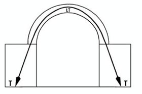 Wider pier |
CATENARY CURVE OF THE LINE OF THRUST
Arches can have various shapes and sizes, but the line of thrust always follows the shape of an inverted catenary curve.
Arches can have various shapes and sizes, but the line of thrust always follows the shape of an inverted catenary curve.
A catenary is the curve assumed by a freely suspended chain or flexible cable under the action of gravity. The centre line of the links is the line of tensile stress. In an arch, the line of thrust is the line of compressive stress and takes the shape of an inverted catenary because it is the curve of natural load transfer in the masonry.
In an arch which has the shape of a perfect inverted catenary curve, the voussoirs correspond to the links of the chain. As the links of the chain are under tension, the voussoirs of the inverted catenary arch are under compression and LT is centred in the voussoirs. Catenary arches are always the most stable so their thickness can be reduced. Segmental arches are also very stable, as LT is near the centre of the arch.
In an arch which has the shape of a perfect inverted catenary curve, the voussoirs correspond to the links of the chain. As the links of the chain are under tension, the voussoirs of the inverted catenary arch are under compression and LT is centred in the voussoirs. Catenary arches are always the most stable so their thickness can be reduced. Segmental arches are also very stable, as LT is near the centre of the arch.
| The line of thrust is centred in the arch only in the case of inverted catenary arches. All the other types of arches will have LT moving in the middle third of the arch thickness, but it will never be centred. Therefore, the arch will be submitted to a combination of compressive and tensile forces, which will tend to induce failure. As LT is the line of compressive stress, the entire arch will be stressed only under compression when LT is close to the centre. When LT moves away from the centre, but still remains in the middle third, this will create a tensile stress on the opposite side of the eccentricity of LT. To optimise the behaviour of an arch, one should try to get LT as close as possible to the centre. |  Catenary curves and arches |
Depending on the load applied on the arch, the line of thrust will assume a particular curve and the arch will be shaped accordingly:
 Example 1: An asymmetrical load is applied |  Example 2: A symmetrical load is applied |
MODIFICATION OF THE LINE OF THRUST IN A WALL
 (Where t is the thickness and S the span)
| The arches shown as examples here are considered to be free standing, meaning without masonry above. Adding some load above the arch will modify the line of thrust in the masonry. LT will become a higher catenary, which often does not pass anymore in the arch but in the masonry above it. Thus the principal line of thrust materializes a discharging arch. Therefore the original arch is supporting only its load and the “triangular load” of the wall, situated below the discharging arch. The arch will still have a line of thrust, and this triangular load will slightly increase its intensity. LT will pass more towards the arch extrados and exit nearer the intrados. |  Modification of LT in a wall |
INFLUENCE OF THE ARCH THICKNESS ON STABILITY
Note that here we use only the name arch but all this approach is also valid for a vault, as an arch generates a vault. We have seen that the line of thrust assumes the shape of an inverted catenary curve and should always remain in the middle third of the arch.
Semicircular arches have a very different profile compared to the catenary curve. Therefore, LT will move far away from the centre and this will create a lot of tensions in the arch. In order to get LT in the middle third of the arch, the thickness should be in relation to the span. Semicircular arches should have a minimum thickness of:
Semicircular arches have a very different profile compared to the catenary curve. Therefore, LT will move far away from the centre and this will create a lot of tensions in the arch. In order to get LT in the middle third of the arch, the thickness should be in relation to the span. Semicircular arches should have a minimum thickness of:
(Where t is the thickness and S the span)Therefore a semicircular arch needs to be very thick to be stable without any load on the haunches: A 6 m span arch requires 1.20 m thickness, so as to get LT at the inner limit of the middle third.
 Instability with too thin an arch: t = S/20 |  Stability with the proper arch thickness: t = S/5 |
This relationship explains why the semicircular barrel vaults need to be very thick, as the haunches cannot always be loaded. Note that the thickness of a semicircular arch can be reduced if the haunches are loaded. This will have three effects:
| 1. LT will enter the middle third of the arch and it will become stable. 2. The load on the haunches will load the pier and bring the thrust more vertical. Thus, the width of the pier can be reduced also. 3. The horizontal thrust is decreased, but the weight and the resultant thrust are increased. |  Reduced thickness with load on the haunches: t = S/10 |
| Similarly, an Egyptian arch needs to be relatively thick to be stable:  (Where t is the thickness and S the span) (Where t is the thickness and S the span)Therefore an Egyptian arch of 5 m span will require 71.5 cm thickness, so as to get LT at the inner limit of the middle third. |  Stability of the Egyptian arch with the proper thickness: t = S/7 |  Proportions of the Egyptian arch , based on the triangle 3,4,5 |
INFLUENCE OF THE MORTAR ON STABILITY
The various methods described hereafter for calculating the stability of arches and vaults don’t take into account the effect of the mortar on the strength of vaulted structures. Calculations are done as if the vaulted structures are built with dry stacked masonry.
The mortar binds the blocks and transmits the compression forces. Note that at the intrados the transmission of forces is directly from block to block: they touch each other. At the extrados the contact is ensured by the mortar which transmits the compression forces.
When vaults and domes are built with the Nubian or Free Spanning techniques, the quality of the mortar is essential to stick the blocks onto each other. But this is needed only while building the structure. Once the structure is completed, the transmission of the forces is also through the mortar, stressed under compression.
Note that cement-sand mortars cannot be used for building vaults and domes without support. Raw earth or stabilised earth mortars are needed to build them this way. Mortars have in general a low tensile strength and they should not be taken into account to give strength to the vaulted structures.
EVALUATION OF THE STABILITY OF DOMES
We saw that domes which are generated by the intersection of two vaults (i. e. groined and cloister domes), have forces identical to those of vaults. Therefore the stability of their arch section can be studied like an arch. These kinds of domes will show a difference from the arches and vaults: they will exert a thrust on four sides and will need a ring beam or abutments to balance it.
When a dome is created by the rotation of an arch around a vertical axis, the circular forces which act in it cannot be yet calculated. Therefore these types of domes require another approach to calculate their stability.
The examples of domes built all over the world through the ages show that domes can have a wider variety of shapes than vaults. For instance, a dome can be conical with any proportions: from a sharp one to a flatter one. But it is obvious that an arch cannot have a triangular section, as a cone is a triangle rotating around a central axis.
 Conical faceted dome |  Conical circular dome |  Triangular arch |
Therefore, it appears that if arches or vaults are stable, domes of the same section will necessarily be stable. But the opposite is not necessarily true, as we have seen with the case of the conical dome and the triangular arch.
| This gives the principle for approaching the stability of circular domes: • The dome is divided into a series of small arches. • The dome is studied like an arch and, when it will be stable, the dome will necessarily be stable. These small arches combine their horizontal thrusts to create a peripheral tension which will tend to crack the wall supporting the dome. This tension can be evaluated. The 22.16 m diameter dome of the Dhyanalinga Temple for Lord Shiva, near Coimbatore-TN-India, was studied with this approach. The dome was built in 9 weeks without any difficulty concerning its stability. The dome stands since January 1999 and no reinforced concrete ring beam had been used for this dome, as it was a requirement from Sadhguru Jaggadish Vasudev. The dome was built on the slope of a hill and was sound till the ground and foundations moved due to the enormous load of the structure: about 1500 tons, which were built in less than 6 months. Three months after completion, the ground – a black clay, settled unevenly and one third of the perimeter of the foundations and wall moved a few millimetres away and down. Thus the dome cracked above this settlement. Since then, the structure stays with some cracks here or there, but the dome, even cracked, stands well. |  Dhyanalinga Temple |